Vectorworks has many extrusion tools each performing a different action which we will look at, but first we must get to grips with the simplest one, the Linear extrusion.
This is an Extrusion that has a single regular profile that has been extruded in one direction only (in a line).
 1.Creating Extrudes
To create basic 3D objects we select a 2D shape and use the extrude tool
(Model>Extrude) to give the object its height or depth, depending on which view you extrude from (front, side or top view).
Care must be taken to extrude in the correct view, we can always rotate the object around afterwards but it is better to get it right first time!.
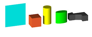
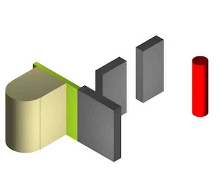
Above: Circle extruded from Front, Right and Top Views
2.Editing Extrusions (Externally):The resulting extrusion can be altered in two ways:
- Manually with the mouse: Drag one of the objects corner or centre control points (make sure that you use the two headed angled arrow cursor). This method is especially useful when alligning an object to another point in your model using the Snapping method.
- Through the Object Info Palette in the box titled 'Extr'
3.Negative Extrusions:We can extrude objects both positively and negatively (e.g 200mm/-200mm).
Try extruding two shapes both
+ and
- in plan view (
0), now move to front view (
2) and see how both objects were created from the same
z height (zero), with one going up and one going down.
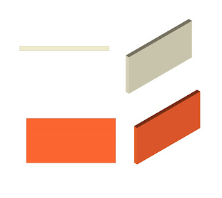
It is useful when creating floors to give them a negative extrusion so that any subsequent extrusions or objects such as chairs or tables will not need to be moved up in elevation but will sit at the right level.4.Extruding Multiple 2D ProfilesWe can extrude multiple 2D shapes at the same time resulting in a single extrusion. Simply select all the shapes prior to extruding.
The benefit of this is that the different shapes may have differing attributes but still belong to the same extrude.
If you want to split the extrusion up into individual 3D objects use the
Modify >Ungroup command.
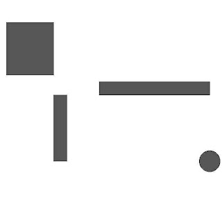 2D Shapes
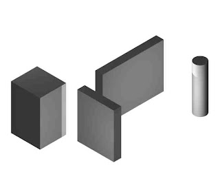
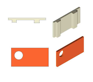
Resulting Extrusion5.Editing Extrusions (Internally)
Although now in a 3D state we can still edit an extrusion in its original 2D form. By double clicking on the object you can
'enter' the extrude and re-shape, add/clip surface etc. It is also possible to add extra 2D shapes or copy and paste in shapes from outside.
 Edited Extrusion
Be careful to exit the extrude by clicking on the '
exit' button to the top-right hand corner of the drawing space. This returns you to the
design-layer where you can continue modeling.
Not doing this is a very common mistake that new users make and can prove frustrating!
The trick to producing efficient extrusions is to work out which view to do the drawing in first, think ahead to what you may do to the object at a later stage.
E.g when drawing walls and partitions, this can be done in two ways
- Top/Plan view and then extruded to give the object a height (Beige object).
- Front view and then extruded to give the object a depth (Red object).
The view we draw in helps us when editing the object further...
- By adding to the original 2D profile using Add surface command.
- By subtracting from the original profile using Clip Surface command.
Work out if you are going to add windows/openings or alcoves/columns.
Copying and Pasting Often in Vectorworks you will need to copy single or multiple objects, this is a simple and often used feature of most graphic packages and works generally the same.
In the
Edit Menu you will find the
Copy,
Paste and
Paste in Place commands.
Soon get into the habit of using the shortcuts for these commands however.
Once you have copied an object the computer will store the information until it has been told to copy something else. Once you have pasted the object you can carry on pasting the object as many times as you wish. It will place the copy on the screen fairly randomly.
The Paste in Place command pastes the object into exactly the same place as the original. This is especially useful when working between layers or even files. It is also useful when copying and pasting into and out of a 3D object or group.
A useful Shortcut for copying an object!Simply hold down the Control (Ctrl) Key when selecting an object and when you drag the mouse away Vectorworks will create a copied version. This works for all objects whether 2D or 3D or multiples of both.
There is a more advanced way of creating copies (using the Duplicate commands), we will look at these in a future lesson dont worry.
If you want though go investigate yourself!


