http://dmae03.blogspot.com/2009/02/drawing-and-editing-walls.html
Working with Layers 2: Layer Visability Settings
http://dmae03.blogspot.com/2009/02/working-with-layers-2.html
2D Attributes
http://dmae03.blogspot.com/2009/01/2d-attributes.html
Exercise 02: 2D Seat Section
The second exercise we will be doing aims to refine your 2D Drawing even further. Using the 2D Re-shape tool we will produce a very accurate trace of a scanned-in technical drawing.
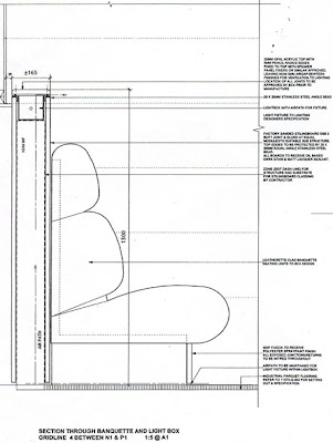
Download the section above to use in the exercise
Using Trace Layers:
You can import plans, elevations, sections etc into Vectorworks and use them as guides to trace or model from.
To import go to File >Import >Import Image File, and select the file that you require. Remember to select an appropriate scale to work in before importing (e.g. if the section is scanned in at 1:10, set the scale in Vectorworks to 1:10 also).
Sometimes the source material will not be to scale or you may not know the scale. in this instance once imported the ‘Bitmap’ must be scaled. We do this by working from a stated dimension on the plan. Draw a line and enter the length in the Object Info Palette. Now select the bitmap and whilst holding down the shift key (to maintain proportion) drag out/in to desired size. Repeat this process until the line matches the dimension).
It is best to leave this plan in its own layer. Go to Tools>Organization >Design Layers, and create a new layer to model in (Trace). The old layer can be renamed Plan Layer.
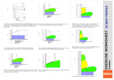
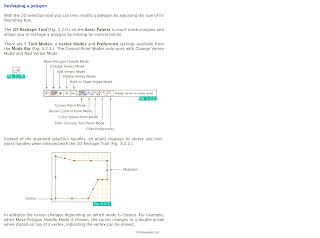
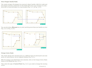
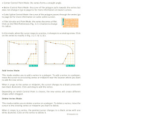
Re-Shaping Polygon Notes:
Read through these notes to help you with the exercise, they can also be downloaded.
Part Two: 3D Modelling
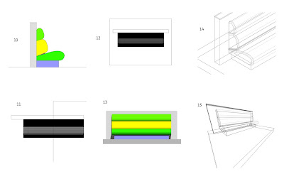
- Base Section =2400mm
- Seat sections = 2500mm
- Wall Section = 3000mm
- At this stage save your work, make a new layer (Name 3D model), and copy and paste a copy of the complete 2D profile into the new layer.
- With the profile copy we can now extrude each part individually to the correct length (First go to the left side view, number 4 on the keyboard number keys). Notice that all of the extrusions extrude from x=0.
- In top view (0), select all the extrusions and align using Modify>Align.
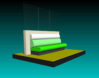
- This is how the seat looks in front elevation
- Use the 3D Fillet edge tool (Tool sets Palette) to smooth the ends of all the seat sections.
- Have a look at the model in 3D. Try out a few different types of Render!
