Monday, 9 November 2009

Session 11: Floors and Ceilings

There is no 'Floor' Tool in Vectorworks as such, instead we draw the floor area using a 2D Tool and then give it a depth (usually a negative extrusion as discussed in session 2). In todays session we will look at two different ways in which to achieve this.
  • Drawing the Floor Area: It is often useful to draw the floor first and then use this as a guide around which to construct the walls. This is especially useful when modeling one room for visualisation. You may have done a site survey and have all of the internal measurements, in this case it is easier to construct an accurate 2D shape for the floor rather than straight away trying to determine the individual lengths of multiple walls.


The Image above shows a floor area made by adding together several rectangles using Modify > Add Surface.

General Tips!
  1. When drawing walls around the Floorplan template make sure that you use the appropriate wall drawing mode from the mode bar. You do not want to have your walls sitting inside the floor area if you have spent time constructing it accurately!
  2. The Floor shapes that you construct can often simply be duplicated and moved up to act as your ceiling object as well!

Advanced Floor Creation:

Vectorworks has even more advanced commands which can be used for quick and easy construction of walls and floors. They are located in the AEC>Architectural menu, found in the Standard Workspace (Tools > Workspaces > Standard Workspace).
  • The Create Polys from Walls command can be used to create flooring and ceilings from multiple walls. Select all of the walls that form contained spaces and access the command (Note that you must select wall objects only for the command to work). Select either Gross or net (room) Polys and see the results.

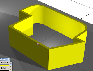
    The Create Walls from Polys Tool takes a polygon and constructs walls around it. The polygon can include curved edges but the program may have trouble with excessively complex shapes. The curved part of the polygon will produce curved walls made up of many individual straight walls. This is different to the curved wall tool which is made of a single wall. This means that it is trickier to position symbols into the wall where desired.
These tools are very useful if you need to draw complex floor shapes and don't feel confident drawing using 2D tools!

Session 11: Drawing Walls

Up to now we have looked at modeling walls using extruded 2D shapes (e.g Double Line Polygon Tool). Vectorworks however has a set of Tools to draw Walls without the need to extrude from 2D to 3D.
  • Walls are part of what we call 'Hybrid Objects'. They display different attributes when in Top/Plan view compared to any 3D view.
  • The Building Shell Sub-Palette (Green Roofed House Icon) is found in the Tool Sets Palette and contains all of the tools needed to construct and edit walls in Vectorworks.
Straight Wall Tool:
This tool works the same as drawing using the normal Polygon tool. Simply click and move the mouse to determine the direction to draw in.
  • To draw a single wall, click, drag and then double click to finish.
  • You may draw multiple walls at one time, simply click, drag click again and then continue to draw a second wall length. Double-Click as normal to finish.
  • All the walls will be selected once you have finished drawing them, this makes it easy to give heights and attributes quickly.
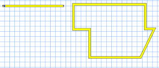

Image above shows a single wall and multiple walls viewed in Top/Plan View

Setting Prefernces and Drawing Modes:
Before drawing walls it is often best to set certain Preferences first and also to decide on which drawing mode to work with. These can all be set through the Mode Bar.

  • Drawing Modes are similar to those of the Double Line Polygon Tool. Each one has a different control method for where the computer places the two wall lines in relation to the mouse on screen.
  • Vectorworks has dozens of Pre-Set Wall styles to choose from in the Wall Preferences Box.
  • For now maybe just worry about using the simple 'default' Wall Style and Pre-setting the Wall thickness only.
Editing Wall Length:
The lengths of walls can be adjusted in two ways:
  • manually by dragging one end of the wall to a new position. Take care to select the correct cursor (double-headed 'angled arrow' cursor). Note that we can also change the angle of the wall this way as well.
  • or in the Obj Info. Palette. Adjust the L value, found under the polar co-ordinates settings. (Note that we can also change the angle of the wall here as well).
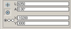

  • We can also Re-position both the end and centre points of a wall on the grid using the x/y settings in the Object Info. Palette.
Editing Settings with the Object Info Palette:
The Object info Palette also contains controls for these other settings:
  • +Z : Sets the overall height of the wall.
  • Bot Z : Sets the height that the wall starts at (Can be both positive and negative).
  • Thick : Sets the thickness of the wall (If changed the wall will alter from its center-line).
  • Caps : Draw lines to 'cap' the start and end of a wall. This is for 2D work only, wall ends will always be solid in 3D.
  • Type: Set the Caps to be either Round or Flat.
Curved Wall Tool:
This tool has many modes and requires a bit of practice to understand but acts just like the straight wall tool in many respects. We will cover this tool in greater depth at a later date!

Wall Join Tool:
We use this tool to join two walls together so that there are no gaps in our 3D model as well as 2D drawing.
  • There are five modes to this tool and each one corresponds to a particular situation, use the diagrams as clues.
  • They all work by clicking on one wall and then drawing a line to the wall to join to.
  • It makes a difference which wall is selected first so if the result is not what you expected try again in another order.



Remove Wall Breaks tool:
  • When splitting or moving walls away from one another a hole may be left in the side of one wall.
  • We can use the Remove Wall Breaks tool (Wall Heal Tool) to fix this. Simply draw a box marquee around the 'break' and it will be filled in.
  • This tool can also be used on walls which have mitred ends resulting from previously being joined to another wall.

Fillet Tool (Basic Palette):
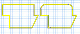


  • Use the fillet tool to produce rounded corners to two walls that meet each other. Select the Fillet mode and Set the Fillet Preferences in the mode bar. In top view click on one wall and then on the second.
  • Try out the three settings for different results. The Fillet can be either 'external' or 'internal'.
General Tips!

  1. Individual and multiple walls can be picked up and moved and you will find that it is often useful to nudge them into place by holding down shift and using the arrow keys.
  2. Take care when editing walls, to lengthen, rotate and move walls requires different cursors. Get to know them and have patience at first when trying to find a particular one!

Session 11: Hybrid Objects

Drawing and Editing Walls:

Straight wall tool
Curved Wall tool
Joining Walls
Filleting walls
Editing Walls in Elevation

Floors and Ceilings:

Drawing a Floor Area
Extruding Floors Negatively
Using the AEC Commands.
Creating Ceilings

Plug-In Objects:
Placing Doors and Windows accurately
Editing Plug-in settings

Working with layers 2:
Layer Visibility settings
Using Snaps between layers
Stacking Layers

Applying Textures 2:
Texturing Walls
Using the Resource Browser Libraries

Session 10 : Case Study 1(Plans)


The Plans above are from Zaha Hadid Architects.
  • They show three floors of the same building and are layed out so that they line up and are to the same scale.
  • They also use a key and colour codes to communicate the different areas and their different uses.
  • Also note the 'void' spaces on each plan where there is no floor area.

Follow the link below for more information....

http://images.google.com/imgres?imgurl=http://news.msu.edu/media/photo/2009/10/38e375ba-02e6-4d3d-9adb-9f08d0d675a5.jpg&imgrefurl=http://broadmuseum.msu.edu/gallery/&usg=__Xq4NyVZ1BTrlw5XzUI_ONrDDsbY=&h=867&w=1400&sz=351&hl=en&start=422&um=1&tbnid=79YdG5vR0Be4CM:&tbnh=93&tbnw=150&prev=/images%3Fq%3Dzaha%2Bhadid%2Bplans%26ndsp%3D20%26hl%3Den%26rlz%3D1B3RNFA_enGB220GB221%26sa%3DN%26start%3D420%26um%3D1

Session 10: Layers and Classes

This sessions exercise is designed to teach you how to set up and organize a model of a multi-story building. It shows how we can use duplicates and symbols to quickly construct the structure and layers and Classes to efficiently organize and present the outcome.

The aim is to follow the worksheet below and then to take the model on further by adding your own individual components.


Below are some renders of the model with the addition of a Renderworks background and a variety of Light sources.

Duplicates and Symbols


·      Duplicates and Symbols

Single Duplicates:
  • You can make a single duplicate of a 2D/3D object by using the Edit> Duplicate command. This will create a duplicate and place it in the same layer as the original.
  • By Default the Duplicate is positioned slightly Up and to the Right of the original. It may be useful to turn off 'off-set duplications' first so that the duplicate is placed in exactly the same positionas the original. You do this through the Tools > Options > Vectorworks Preferences Menu.
  • When you edit a Duplicate it will have no effect on the Original Object!
Multiple Duplicates:
  • For more Advanced Duplications we can use the Edit > Duplicate Array Command.
  • The Edit > Duplicate Array command has three extra modes which all have their specific types of Duplicate Creation (Linear, rectangular and circular).
  • These all work by specifying the number of Duplicates to be created and imputing data for movement in x,y and z co-ordinates (Z is for 3D so don’t worry for now!).
  • After carrying out a duplicate array it is often useful to Group the results so that they can be selected, moved etc with ease (Modify > Group).
  • There are even more advanced Duplication methods such as the option of Re-Sizing and Rotating when Duplicating so try them out!

Symbols 1:

Any object that will be repeated throughout your model should generally be first made into a symbol (Chairs, tables, taps, floortiles, pillars etc.).
You can even make symbols out of multiple objects (say a bedroom scheme for a 200 room hotel!).
This way you can come up with large design schemes fairly quickly and update your scheme as your design develops with limited remodeling required.
  • When making duplicates it often makes sense to make a symbol out of the object first. (Modify> Create Symbol)
  • Creating Symbols means that you can now edit one symbol and it will automatically update all of the others.To edit a symbol simply double-click on any one ‘Instance’.
  • When creating a symbol remember to tick the ‘Leave Instance in place box’ otherwise your symbol will disappear from the screen and you will need to find it in the Resource Browser Palette.

We will be using symbols in more detail in later sessions so do not worry too much if it seems confusing to begin with!


Exercise 03 : Duplication

-Draw out the simple Floorplan below using the Duplicate Array Tool (consider the different modes of Duplication).
-Before Duplicating create symbols out of each component part.


PROJECT TWO : Information


BRIEFING NOTES

Additional information agreed the apartment project
Briefing on Monday 2/11/9.

  • The site is based on the street gallery, but dimensions can be rounded up to 10m x 10m. 6m is the max height but not the norm.
  • The aspect is the same ie. North is the student bar direction.
  • The entrance to the apartment is on the east wall and can be situated anywhere along that wall.
  • You may add any wall openings along all walls except the east entrance wall.
  • You may add openings / rooflights to the ceiling.
  • You may add balconies/ patios to a “reasonable” size.
  • Students are to draw a floorplan of the layout of the entire space, but focus their design on the living area and 1 other area.
  • Perspectives should be of the living area and 1 other area
  • The sample board should be actual samples where possible and one or two photos max. of the chosen areas ie living area and/ or 1 other area.
  • The design can be compartments or totally open plan (except for bathroom WC. which is compartmented)