Wednesday, 28 October 2009
Session 8: Viewports 1
Once you have a model you will need to present it. Vectorworks has what are called Viewports and Sheet Layers in which to do this (like architectural technical drawing layouts).
Viewport Creation
To create a Viewport select the objects that are to be presented and go to View >Create Viewport. The objects are then re-presented on a new 'Sheet Layer' as 2D Images.
You can create a Viewport from any Standard View, in any scale,render or even in Perspective. You can take as many Viewports through to a sheet as you wish, although sometimes it is easier to simply take one through and copy it as many times as needed as we can always change their settings afterwards.
Editing Viewports
Once in the Sheet Layer, Viewports can be edited through the Object Info Pallette. We can change the view, scale, render and perspective of a particular viewport. The Viewport may need to be updated afterwards if a red line appears around it, to do this go to View >Update Viewports (or select Update in the Obj. Info Palette).
By double-clicking on a Viewport you can edit it further, either by adding annotations, dimensions or by cropping (useful for showing design details and framing perspective views).
Arrange your sheet layers like architectural layout pages with your plan bottom left and elevation directly above. We can add a drawing border and title block in the bottom right hand corner (Tool Sets Palette > Dimensions and Notes).
As well as using Vectorworks own Page Layout Tools it is often a more exciting Graphic approach to add in your own layout elements. Try adding Text for Titles, 2D Shapes for backgrounds or even import Images and Photographs to use in your Presentation Pages.
Tip: The adding of text and Images from other packages (Word, Works etc, or even straight from the Web) can be done simply by copying and pasting into the Sheet Layer. This makes it quick and easy to anotate your work.
As you continue to work on your model the sheet layers will automatically update!
Viewport Creation
To create a Viewport select the objects that are to be presented and go to View >Create Viewport. The objects are then re-presented on a new 'Sheet Layer' as 2D Images.
You can create a Viewport from any Standard View, in any scale,render or even in Perspective. You can take as many Viewports through to a sheet as you wish, although sometimes it is easier to simply take one through and copy it as many times as needed as we can always change their settings afterwards.
Editing Viewports
Once in the Sheet Layer, Viewports can be edited through the Object Info Pallette. We can change the view, scale, render and perspective of a particular viewport. The Viewport may need to be updated afterwards if a red line appears around it, to do this go to View >Update Viewports (or select Update in the Obj. Info Palette).
By double-clicking on a Viewport you can edit it further, either by adding annotations, dimensions or by cropping (useful for showing design details and framing perspective views).
- Anotations can include all textual notes as well as any extra 2D line/shape work that needs to be added over the top of a viewport.
- Dimensions should only be added within the viewport, adding them to the Sheet Layer will create them to the Layers paper scale (1:1) and not the viewports scale.
- Crops are created using any 2D Shape (circles, rectangles or polygons/polylines etc). Sometimes you may wish to have a borderless crop, simply set the Pen Line setting to none for the Crop Object.
Arrange your sheet layers like architectural layout pages with your plan bottom left and elevation directly above. We can add a drawing border and title block in the bottom right hand corner (Tool Sets Palette > Dimensions and Notes).
As well as using Vectorworks own Page Layout Tools it is often a more exciting Graphic approach to add in your own layout elements. Try adding Text for Titles, 2D Shapes for backgrounds or even import Images and Photographs to use in your Presentation Pages.
Tip: The adding of text and Images from other packages (Word, Works etc, or even straight from the Web) can be done simply by copying and pasting into the Sheet Layer. This makes it quick and easy to anotate your work.
As you continue to work on your model the sheet layers will automatically update!
Tuesday, 20 October 2009


Monday, 19 October 2009
Session 7: Applying Textures 1
The addition of textures and other graphics to your model will make a huge difference and help bring it to life. Today we will look at a few specific tools and tricks, however there are too many to mention here. the best way to learn is to experiment yourself with all the options and to have fun doing so!
Object Info Palette:
The application of basic textures is done through the Object Info Palette under the Render Tab. Select a 3D object and then in th Render Tab select a texture from the pull down menu. Most of these pre-set textures come already scaled. A brick will map onto the surface of an object at its correct size.
Resource Browser libraries:
There are also a wide variety of textures in the Resource Browser Palette to choose from. Select the type of texture required ( e.g Interior textures) and then you are given a full range of textures for that category.
To apply these textures simply select the object and double click on the required texture icon.
Note that once you have used a texture it will now be placed in the Object Info Palette, Render Tab list for you to use.
Session 7: Render Modes
There are many types of Render that can be used but these are the 3 that you will use at first, and most regularly:
To activate a particular Render go to View>Rendering (or select from the Render style Icon in the Data Display Bar).
Open GL:
This is a very useful type of render which allows you to navigate through the model in real time whilst maintaining the render on screen. It shows colour and lighting attributes. The shadows and textures will be of a lower quality however.
Final Quality Render:
This is the best type of render available in Vectorworks and shows all textures, shadows, reflections and transparencies. It will take the longest time to render in Final Quality but makes it possible to achieve photo-realistic results.
Hidden Line:
This render produces very basic black and white forms without shadows. It can be used for producing plans, sections and elevations as well as simple 3D views that can then be sketched over.


Wednesday, 14 October 2009
Session 6: Exporting from Vectorworks
One way of getting your drawing/model from vectorworks is to print straight from the program. Alternatively we can export out the information as still images. these can then be printed, re-sized, emailed etc.
Exporting to Scale:
Exporting in Perspective:
To export one of your saved views (or any other perspective view) go to;
File> Export> Export Image File
Here we can ask the computer to render and export 'Current view', this will export only what is contained with-in the viewing space. You should therefore compose the dimension of the export first and frame it on the screen using the zoom tools. Also note that it will export in whichever render mode you have on the screen.
Resolution:
Depending on the time available and the use of the render we can export out at any given resolution. For good quality renders I suggest at least 200dpi. for line work at least 150dpi.
The best thing to do is to test the quality for each model. the more lights and textures that you have the longer the render is going to take. it is not unusual for some renders to take as long as 1 hour!
Print Size:
Here we can set the export print size. As the ratio is already set in the saved view we only need to input a value for either width or height not both (e.g 420mm width for an A3 landscape export).
File type:
Select from a wide range of file types. I suggest jpeg or tiff for now.
When you have set all of the required fields, click save and give the render a name and select where to save to.
Exporting to Scale:
- The best way to export to scale is as a PDF Document, go to File> Export> Export PDF
This will again export what is inside the page boundary only (the default resolution of 300dpi is used). PDF documents export line drawings at a better quality than other export file types and produce more accurate line thicknesses.
- Another way to export your model to scale go to; File> Export> Export Image File
Now we can select 'Each Page as seperate Image'. This means that only what is inside the page boundary will be exported and that it will be exported at the pre-set page size automatically.
We still have to set the resolution and file type (for line drawings 240dpi should be sufficient).
Exporting in Perspective:
To export one of your saved views (or any other perspective view) go to;
File> Export> Export Image File
Here we can ask the computer to render and export 'Current view', this will export only what is contained with-in the viewing space. You should therefore compose the dimension of the export first and frame it on the screen using the zoom tools. Also note that it will export in whichever render mode you have on the screen.
Resolution:
Depending on the time available and the use of the render we can export out at any given resolution. For good quality renders I suggest at least 200dpi. for line work at least 150dpi.
The best thing to do is to test the quality for each model. the more lights and textures that you have the longer the render is going to take. it is not unusual for some renders to take as long as 1 hour!
Print Size:
Here we can set the export print size. As the ratio is already set in the saved view we only need to input a value for either width or height not both (e.g 420mm width for an A3 landscape export).
File type:
Select from a wide range of file types. I suggest jpeg or tiff for now.
When you have set all of the required fields, click save and give the render a name and select where to save to.
Session 5: Documenting Development
Documenting Development:
Now it is time to apply what you have practised to your own design. Don’t think too much just try it out and then judge the results.
Even ideas that don’t work are good ideas because they show the working out of an idea.
Now it is time to apply what you have practised to your own design. Don’t think too much just try it out and then judge the results.
- In the Tool Sets Palette there is a Visualisation Sub-Palette (Light Bulb Symbol). Here you will find the Render Bitmap Tool. This is your ‘digital camera’ which we use to take snapshots of our model at different stages of construction.
- Simply drag a marquee around the area to render and it will take a picture (called Bitmap). These will never change. By default the Render Bitmap Tool uses the Open GL render Mode (this can be changed in the Mode Bar).
- It is a good idea to store these pictures on a separate Layer. Make a new Layer and through the Object Info. Palette move the Renders between layers.
- You should now arrange the Bitmaps on the new Layers page. They can also be re-scaled (remember to hold down the Shift Key to maintain proportions).
- This page of Renders can now be printed or exported out of Vectorworks as a PDF or JPEG and used in your Design Development Portfolio to show the progression of your ideas. For Exporting read the Blog notes (Exporting / Printing)
- Remember that the more material you get out of the program the more you will have to work with and show at tutorials.
Even ideas that don’t work are good ideas because they show the working out of an idea.
Tuesday, 13 October 2009
Session 5: 3D Boolean Operations
We have looked at many ways of creating complex 2D forms from multiple 2D shapes using Add/Clip Surface. These are what we call 'Boolean' forms (made from adding / subtracting two or more shapes.
In Vectorworks you can also create Boolean objects by using two 3D objects as your starting point, this is what we term Solid Modelling.
Model Menu :
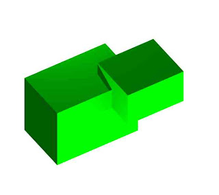
Solid Addition
Select two or more overlapping solids and use the Model >Add solid command to combine into one new ‘Solid Addition’.
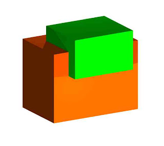
Solid Subtraction
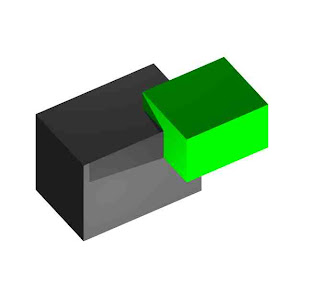
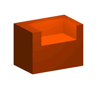
Select two overlapping solids and use the Model >Subtract Solid command to create one new ‘Solid Subtraction’.
Editing Booleans
You can edit a Solid Addition/Subtraction by double-clicking on the object. Once 'inside' you can move the individual objects around and also edit the forms of the individual solids.
To add to/subtract further from an Solid Addition/Subtraction it is not needed to repeat the whole process using the Model menu commands.
You can simply model the extra objects 'inside' the Addition/Subtraction and the computer will do the job for you.
Exit the Addition/Subtraction to see the results.
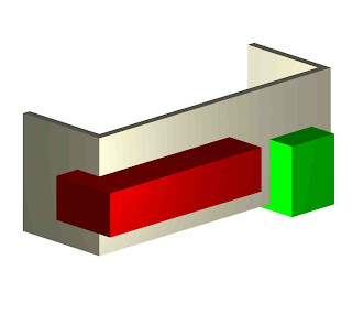
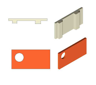
To cut a hole right through a 3D object make sure that the 'cutter' object extrudes completely through, past the edges of the other object. It does not matter how far past it extrudes just as long as it does!
In Vectorworks you can also create Boolean objects by using two 3D objects as your starting point, this is what we term Solid Modelling.
Model Menu :
Solid Addition
Select two or more overlapping solids and use the Model >Add solid command to combine into one new ‘Solid Addition’.


Solid Subtraction
Select two overlapping solids and use the Model >Subtract Solid command to create one new ‘Solid Subtraction’.


Editing Booleans
You can edit a Solid Addition/Subtraction by double-clicking on the object. Once 'inside' you can move the individual objects around and also edit the forms of the individual solids.


To add to/subtract further from an Solid Addition/Subtraction it is not needed to repeat the whole process using the Model menu commands.
You can simply model the extra objects 'inside' the Addition/Subtraction and the computer will do the job for you.
Exit the Addition/Subtraction to see the results.


To cut a hole right through a 3D object make sure that the 'cutter' object extrudes completely through, past the edges of the other object. It does not matter how far past it extrudes just as long as it does!
Add Surface / Clip Surface Commands
Modify Menu 1
When constructing 2D shapes it is often impossible or more difficult to draw them in one go. Therefore we must construct a new shape from two or more separate ones. Fairly complex polygons can be created in this way, either by adding or subtracting elements together. The commands required are located in the Modify Pull-down menu.
Add Surface
Select two or more overlapping (or touching) shapes and add together (Modify>Add surface). The resulting polygon takes on the attributes of the shape furthest to the back in the stacking order.
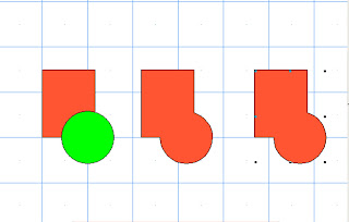
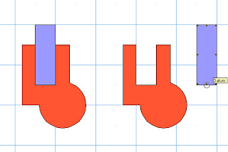
Clip Surface
Select two overlapping 2D shapes and use one to clip the other (Modify>Clip Surface). Notice that the top shape always acts as the ‘cutter’. The resulting polygon keeps its attributes. You can either delete, move or do nothing to the ‘cutter’. In the example below the 'cutter' has been moved away to show the resulting clip.
When constructing 2D shapes it is often impossible or more difficult to draw them in one go. Therefore we must construct a new shape from two or more separate ones. Fairly complex polygons can be created in this way, either by adding or subtracting elements together. The commands required are located in the Modify Pull-down menu.
Add Surface
Select two or more overlapping (or touching) shapes and add together (Modify>Add surface). The resulting polygon takes on the attributes of the shape furthest to the back in the stacking order.

Clip Surface
Select two overlapping 2D shapes and use one to clip the other (Modify>Clip Surface). Notice that the top shape always acts as the ‘cutter’. The resulting polygon keeps its attributes. You can either delete, move or do nothing to the ‘cutter’. In the example below the 'cutter' has been moved away to show the resulting clip.

Session 5: Moving Objects in 3D
There are a number of ways to move objects in Vectorworks, some are more accurate than others but all will prove useful at some time. To move efficiently it is important to have a clear understanding of three-dimensional space and its co-ordinate system.
- Modify>Move (Ctrl M): To move an object or multiple objects accurately we can use this command. type in numerical distances for either x/y or both. We can use both positive and negative distances (to move an object up make sure you are in either a front, back or side view).
- Manually with the mouse: Simply selecting and moving an object is useful but for more accuracy make sure that you select an object by the 'crosshair' cursor, this allows you to align that point with another point in your model (even when in an isometric view!).
- Arrow keys: Select an object, hold down the shift key and use the 'nudge' arrows on the keyboard. This will move an object in one direction only. This is good for making small adjustments to an objects position (If you have to move objects over a large distance, try zooming out further so that the objects move quicker).
- Object info. Palette: You can reposition objects using their x/y/z co-ordinate position on the drawing grid.
Session 5: Basic Extrusions
Vectorworks has many extrusion tools each performing a different action which we will look at, but first we must get to grips with the simplest one, the Linear extrusion.
This is an Extrusion that has a single regular profile that has been extruded in one direction only (in a line).
1.Creating Extrudes
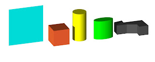
To create basic 3D objects we select a 2D shape and use the extrude tool (Model>Extrude) to give the object its height or depth, depending on which view you extrude from (front, side or top view).
Care must be taken to extrude in the correct view, we can always rotate the object around afterwards but it is better to get it right first time!.
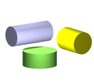
Above: Circle extruded from Front, Right and Top Views
2.Editing Extrusions (Externally):
The resulting extrusion can be altered in two ways:
We can extrude objects both positively and negatively (e.g 200mm/-200mm).
Try extruding two shapes both + and - in plan view (0), now move to front view (2) and see how both objects were created from the same z height (zero), with one going up and one going down.
It is useful when creating floors to give them a negative extrusion so that any subsequent extrusions or objects such as chairs or tables will not need to be moved up in elevation but will sit at the right level.
4.Extruding Multiple 2D Profiles
We can extrude multiple 2D shapes at the same time resulting in a single extrusion. Simply select all the shapes prior to extruding.
The benefit of this is that the different shapes may have differing attributes but still belong to the same extrude.
If you want to split the extrusion up into individual 3D objects use the Modify >Ungroup command.
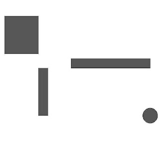
2D Shapes
Resulting Extrusion
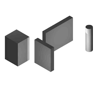
5.Editing Extrusions (Internally)
Although now in a 3D state we can still edit an extrusion in its original 2D form. By double clicking on the object you can 'enter' the extrude and re-shape, add/clip surface etc. It is also possible to add extra 2D shapes or copy and paste in shapes from outside.
Edited Extrusion
Be careful to exit the extrude by clicking on the 'exit' button to the top-right hand corner of the drawing space. This returns you to the design-layer where you can continue modeling.
Not doing this is a very common mistake that new users make and can prove frustrating!
The trick to producing efficient extrusions is to work out which view to do the drawing in first, think ahead to what you may do to the object at a later stage.
E.g when drawing walls and partitions, this can be done in two ways
The view we draw in helps us when editing the object further...
Work out if you are going to add windows/openings or alcoves/columns.
Copying and Pasting
Often in Vectorworks you will need to copy single or multiple objects, this is a simple and often used feature of most graphic packages and works generally the same.
In the Edit Menu you will find the Copy, Paste and Paste in Place commands.
Soon get into the habit of using the shortcuts for these commands however.
Once you have copied an object the computer will store the information until it has been told to copy something else. Once you have pasted the object you can carry on pasting the object as many times as you wish. It will place the copy on the screen fairly randomly.
The Paste in Place command pastes the object into exactly the same place as the original. This is especially useful when working between layers or even files. It is also useful when copying and pasting into and out of a 3D object or group.
A useful Shortcut for copying an object!
Simply hold down the Control (Ctrl) Key when selecting an object and when you drag the mouse away Vectorworks will create a copied version. This works for all objects whether 2D or 3D or multiples of both.
There is a more advanced way of creating copies (using the Duplicate commands), we will look at these in a future lesson dont worry. If you want though go investigate yourself!
This is an Extrusion that has a single regular profile that has been extruded in one direction only (in a line).

1.Creating Extrudes
To create basic 3D objects we select a 2D shape and use the extrude tool (Model>Extrude) to give the object its height or depth, depending on which view you extrude from (front, side or top view).
Care must be taken to extrude in the correct view, we can always rotate the object around afterwards but it is better to get it right first time!.

Above: Circle extruded from Front, Right and Top Views
2.Editing Extrusions (Externally):
The resulting extrusion can be altered in two ways:
- Manually with the mouse: Drag one of the objects corner or centre control points (make sure that you use the two headed angled arrow cursor). This method is especially useful when alligning an object to another point in your model using the Snapping method.
- Through the Object Info Palette in the box titled 'Extr'
We can extrude objects both positively and negatively (e.g 200mm/-200mm).
Try extruding two shapes both + and - in plan view (0), now move to front view (2) and see how both objects were created from the same z height (zero), with one going up and one going down.
It is useful when creating floors to give them a negative extrusion so that any subsequent extrusions or objects such as chairs or tables will not need to be moved up in elevation but will sit at the right level.
4.Extruding Multiple 2D Profiles
We can extrude multiple 2D shapes at the same time resulting in a single extrusion. Simply select all the shapes prior to extruding.
The benefit of this is that the different shapes may have differing attributes but still belong to the same extrude.
If you want to split the extrusion up into individual 3D objects use the Modify >Ungroup command.

2D Shapes

Resulting Extrusion
5.Editing Extrusions (Internally)
Although now in a 3D state we can still edit an extrusion in its original 2D form. By double clicking on the object you can 'enter' the extrude and re-shape, add/clip surface etc. It is also possible to add extra 2D shapes or copy and paste in shapes from outside.

Edited Extrusion
Be careful to exit the extrude by clicking on the 'exit' button to the top-right hand corner of the drawing space. This returns you to the design-layer where you can continue modeling.
Not doing this is a very common mistake that new users make and can prove frustrating!
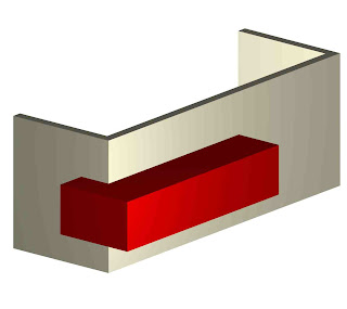
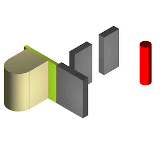
The trick to producing efficient extrusions is to work out which view to do the drawing in first, think ahead to what you may do to the object at a later stage.
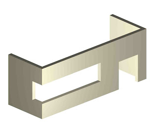
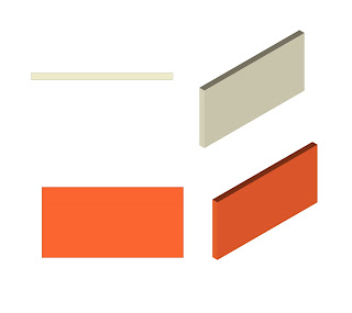
E.g when drawing walls and partitions, this can be done in two ways
- Top/Plan view and then extruded to give the object a height (Beige object).
- Front view and then extruded to give the object a depth (Red object).

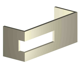
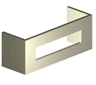
The view we draw in helps us when editing the object further...
- By adding to the original 2D profile using Add surface command.
- By subtracting from the original profile using Clip Surface command.

Work out if you are going to add windows/openings or alcoves/columns.
Copying and Pasting
Often in Vectorworks you will need to copy single or multiple objects, this is a simple and often used feature of most graphic packages and works generally the same.
In the Edit Menu you will find the Copy, Paste and Paste in Place commands.
Soon get into the habit of using the shortcuts for these commands however.
Once you have copied an object the computer will store the information until it has been told to copy something else. Once you have pasted the object you can carry on pasting the object as many times as you wish. It will place the copy on the screen fairly randomly.
The Paste in Place command pastes the object into exactly the same place as the original. This is especially useful when working between layers or even files. It is also useful when copying and pasting into and out of a 3D object or group.
A useful Shortcut for copying an object!
Simply hold down the Control (Ctrl) Key when selecting an object and when you drag the mouse away Vectorworks will create a copied version. This works for all objects whether 2D or 3D or multiples of both.
There is a more advanced way of creating copies (using the Duplicate commands), we will look at these in a future lesson dont worry. If you want though go investigate yourself!
Wednesday, 7 October 2009
Session 4: 3D Navigation
Vectorworks is a highly powerful piece of 3D software and it is vital that you get the most out of your model, not just in terms of technical drawings but also in three-dimensional visualisations. Here are some of the initial steps to consider when visualising your model:
Views:
Using the View Pull-down menu or the keyboard shortcuts (0-9) we can navigate around the model in 3D. This can be done in Isometric and Perspective and in all types of Render. It is important to understand which number corresponds to which view. Think of your model as being number five surrounded by all the other views!.
0 : Top/Plan
1 : Left Isometric
2 : Front
3 : Right Isometric
4 : Left
5 : Top
6 : Right
7 : Left Rear Isometric
8 : Back
9 : Right Rear Isometric
Perspective:
The perspective is set through View>Perspective. It can be set to narrow, normal and wide. Once set you can edit the viewing space on the screen by pulling the black corner controls around. If the perspective of your model is too distorted try changing to a larger scale first.
Set 3D View:
To have more control over the Perspective view use this tool. We can now decide on the exact position, height and angle of view. Consider setting up views at eye-levels or entrances,
Fly-Over Tool:
Use this tool to move through 3D Space by orbiting completely around your model.
Once you have found a view that you like use the Saved View Command in the Views Menu. Give it a name that you will remember and perhaps save the same view in different types of render.
Tuesday, 6 October 2009
Session 3: 2D 2 (Trace Layers)
Working with Layers 1 : Setting up a New Layer
http://dmae03.blogspot.com/2009/02/drawing-and-editing-walls.html
Working with Layers 2: Layer Visability Settings
http://dmae03.blogspot.com/2009/02/working-with-layers-2.html
2D Attributes
http://dmae03.blogspot.com/2009/01/2d-attributes.html
Exercise 02: 2D Seat Section
The second exercise we will be doing aims to refine your 2D Drawing even further. Using the 2D Re-shape tool we will produce a very accurate trace of a scanned-in technical drawing.
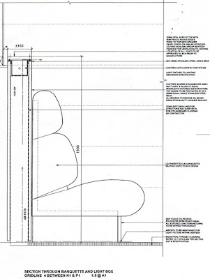
Download the section above to use in the exercise
Using Trace Layers:
You can import plans, elevations, sections etc into Vectorworks and use them as guides to trace or model from.
To import go to File >Import >Import Image File, and select the file that you require. Remember to select an appropriate scale to work in before importing (e.g. if the section is scanned in at 1:10, set the scale in Vectorworks to 1:10 also).
Sometimes the source material will not be to scale or you may not know the scale. in this instance once imported the ‘Bitmap’ must be scaled. We do this by working from a stated dimension on the plan. Draw a line and enter the length in the Object Info Palette. Now select the bitmap and whilst holding down the shift key (to maintain proportion) drag out/in to desired size. Repeat this process until the line matches the dimension).
It is best to leave this plan in its own layer. Go to Tools>Organization >Design Layers, and create a new layer to model in (Trace). The old layer can be renamed Plan Layer.
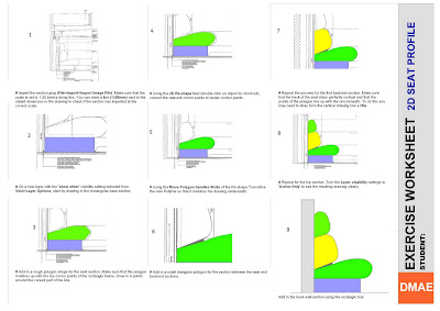
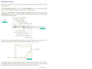
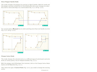
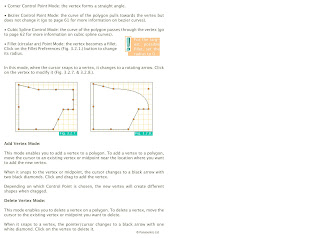
Re-Shaping Polygon Notes:
Read through these notes to help you with the exercise, they can also be downloaded.
Part Two: 3D Modelling
http://dmae03.blogspot.com/2009/02/drawing-and-editing-walls.html
Working with Layers 2: Layer Visability Settings
http://dmae03.blogspot.com/2009/02/working-with-layers-2.html
2D Attributes
http://dmae03.blogspot.com/2009/01/2d-attributes.html
Exercise 02: 2D Seat Section
The second exercise we will be doing aims to refine your 2D Drawing even further. Using the 2D Re-shape tool we will produce a very accurate trace of a scanned-in technical drawing.

Download the section above to use in the exercise
Using Trace Layers:
You can import plans, elevations, sections etc into Vectorworks and use them as guides to trace or model from.
To import go to File >Import >Import Image File, and select the file that you require. Remember to select an appropriate scale to work in before importing (e.g. if the section is scanned in at 1:10, set the scale in Vectorworks to 1:10 also).
Sometimes the source material will not be to scale or you may not know the scale. in this instance once imported the ‘Bitmap’ must be scaled. We do this by working from a stated dimension on the plan. Draw a line and enter the length in the Object Info Palette. Now select the bitmap and whilst holding down the shift key (to maintain proportion) drag out/in to desired size. Repeat this process until the line matches the dimension).
It is best to leave this plan in its own layer. Go to Tools>Organization >Design Layers, and create a new layer to model in (Trace). The old layer can be renamed Plan Layer.

Re-Shaping Polygon Notes:
Read through these notes to help you with the exercise, they can also be downloaded.


Part Two: 3D Modelling

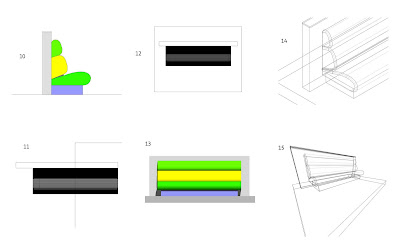
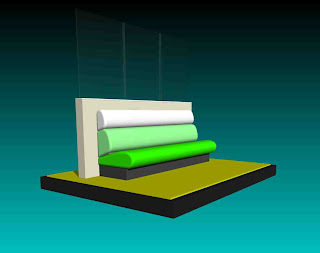
- Base Section =2400mm
- Seat sections = 2500mm
- Wall Section = 3000mm
- At this stage save your work, make a new layer (Name 3D model), and copy and paste a copy of the complete 2D profile into the new layer.
- With the profile copy we can now extrude each part individually to the correct length (First go to the left side view, number 4 on the keyboard number keys). Notice that all of the extrusions extrude from x=0.
- In top view (0), select all the extrusions and align using Modify>Align.
- This is how the seat looks in front elevation
- Use the 3D Fillet edge tool (Tool sets Palette) to smooth the ends of all the seat sections.
- Have a look at the model in 3D. Try out a few different types of Render!

Subscribe to:
Posts (Atom)